
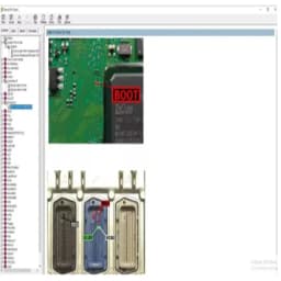
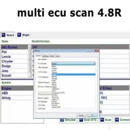
ECU Pinouts Collection: Photo Repair Guide + PDF Instructions Car Repair Tool with ECU Pinout Maps versus ALLDATA for Automotive
53.51$
16.06$
Quantity:
1
Availability:
Out of StockColor
Ships From
Language
Card Payments
Crypto Payments
Easy return
Reliable Shipping
ECU Pinouts Collection: Photo Repair Guide + PDF Instructions Car Repair Tool with ECU Pinout Maps versus ALLDATA for Automotive
Photo Repair Guide Included
The package comes with a photo repair guide, making it easier for users to understand and apply the ECU pinout maps effectively.
Comprehensive ECU Pinouts Collection
This diagnostic tool offers a comprehensive collection of ECU pinouts, providing detailed information for efficient car repairs.
Certified by CE
This diagnostic tool is certified by CE, ensuring its safety and reliability for automotive repairs.
Versus ALLDATA Feature
The tool stands out by offering features versus ALLDATA, giving users a competitive advantage in automotive diagnostics.
PDF Instructions for Reference
In addition to the photo guide, PDF instructions are provided for users to refer to, ensuring clear guidance on car repairs.
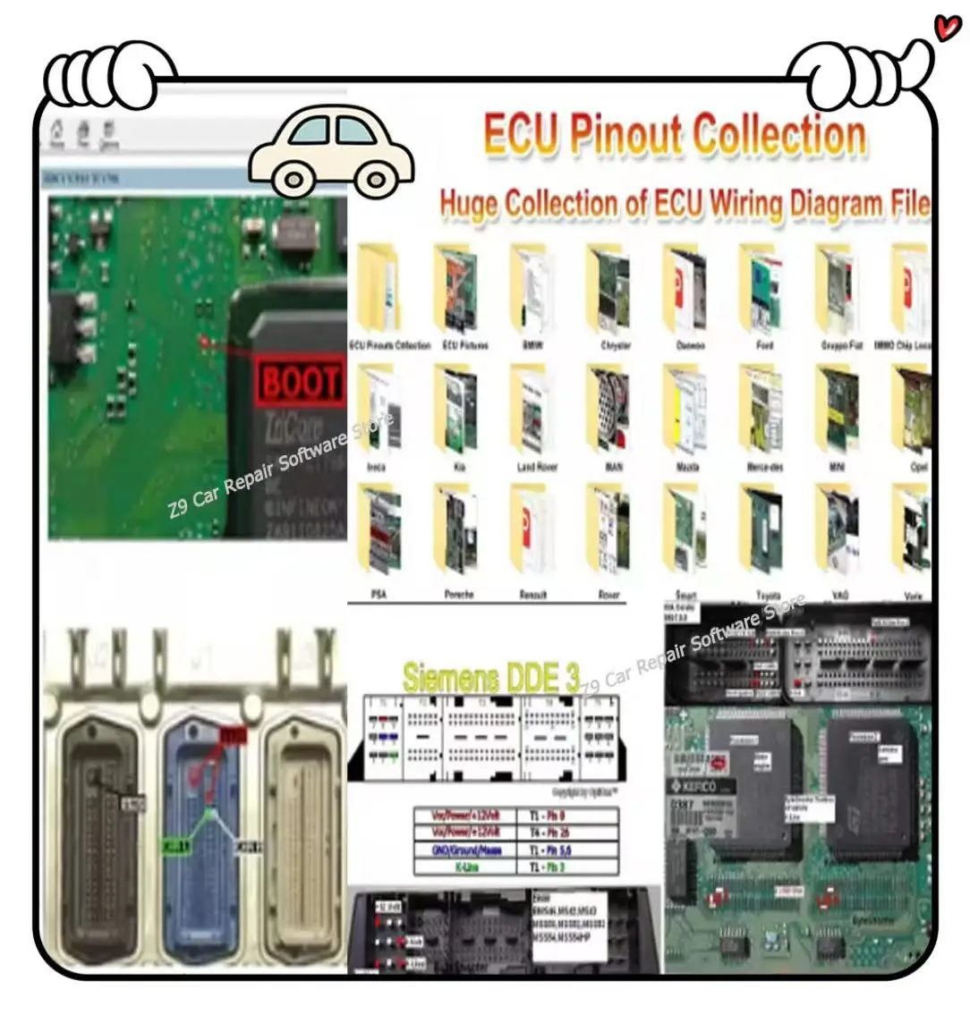
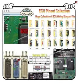
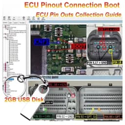
Huge Ecu Pinout Collection of ECU Pinout Files!
ECU Pinout offers a comprehensive collection of ECU pinout diagrams for various vehicle makes and models. You can search for specific ECUs or browse through the available categories. Some vehicle manufacturers provide official documentation, including ECU pinout diagrams, in their service manuals or technical resources.
What is a Pinout?
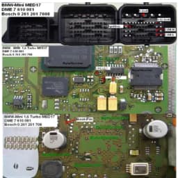
A pinout, also known as a wiring diagram or connector diagram, illustrates the connections and functions of the pins on an electronic device, such as an ECU. Pinouts are essential in diagnosing and troubleshooting electronic systems, as they provide valuable information on power supply, ground connections, sensor inputs, and output signals.
Understanding Pinout Diagrams
Pinout diagrams typically consist of tables with rows and columns, providing information on pin numbers, functions, voltage levels, and signal types. Let’s delve into each component of a pinout diagram:
Pin Number:
Each pin on the ECU has a unique number, facilitating easy identification and reference.
Function: This column describes the purpose or role of each pin, such as power supply, ground, sensor input, or output signal.
Voltage Levels: Pinout diagrams specify the voltage levels for power and ground pins, which is crucial for proper functioning of the ECU.
Signal Types:
These diagrams also indicate the types of signals transmitted through certain pins, such as analog, digital, or PWM (Pulse Width Modulation).
Benefits of Using Pinout Diagrams
Advantages when working with Bosch ECUs:
Easy Troubleshooting
Pinout diagrams simplify the process of identifying faulty connections or components, saving time and effort.
Accurate Diagnosis
By understanding the pin functions and voltage levels, technicians can accurately diagnose issues and make necessary repairs.
Efficient Tuning
Pinout diagrams aid in the tuning and modification of ECUs, ensuring optimal performance and compatibility with aftermarket components.
ECU Swapping
When replacing a damaged ECU, having access to the pinout diagram ensures the correct connections are made, preventing further damage or compatibility issues.

Customer Reviews
No reviews yet
ECU Pinouts Collection: Photo Repair Guide + PDF Instructions Car Repair Tool with ECU Pinout Maps versus ALLDATA for Automotive
53.51$
16.06$
Quantity:
1
Availability:
Out of StockColor
Ships From
Language