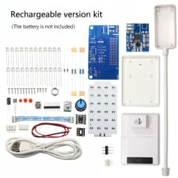
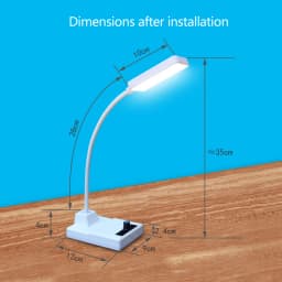
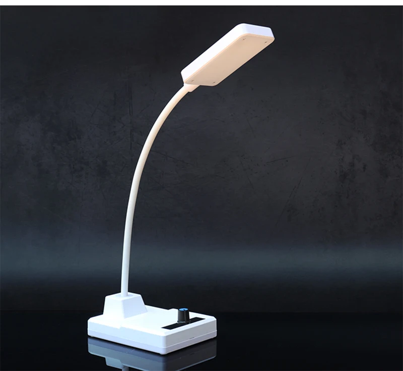
DIY Electronic Kit NE555 LED Dimming Table Lamp Kit PWM Circuit DIY Soldering Assembly 8.5W 5V 2A With Switch Potentiometer
51.32$
25.66$
Quantity:
1
Availability:
Color
Card Payments
Crypto Payments
Easy return
Reliable Shipping
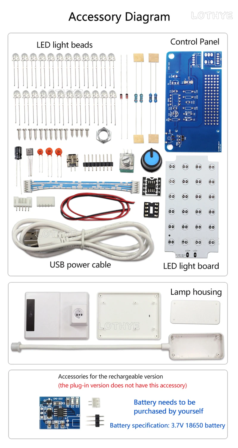
The products which are suitable for electronic enthusiasts to study and repair circuits. We only guarantee that the products are in good condition before delivery, and cannot guarantee 100% success after installation. The installation of the circuit requires the buyer to have experience in the circuit, please read the product description carefully before payment.
Batteries are not included in the accessories
Product parameters
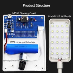
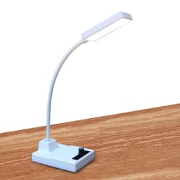
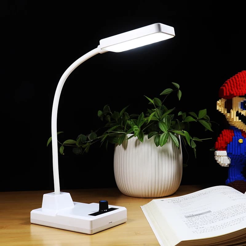
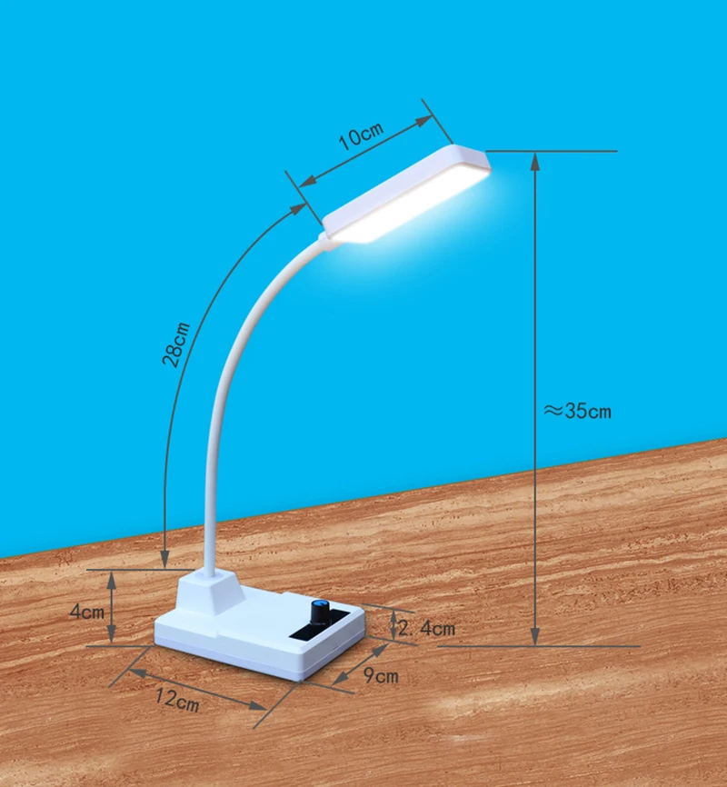
Product Name: 555LED Dimmable Desk Lamp DIY Kit
Power: 8.5W (Plug-in model)
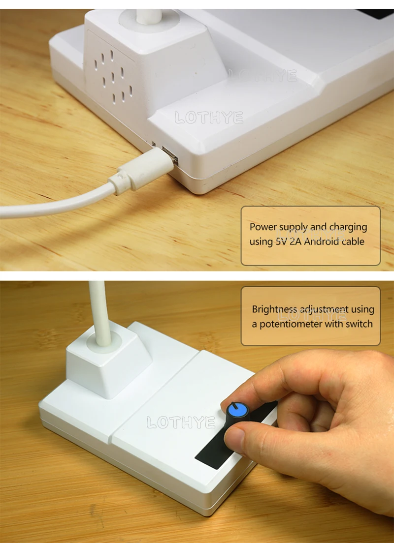
power supply: 5V 1.7A
Power supply cable: USB-Micro1m 2A
Lamp beads: 24pcs 0.5W 5mm straw hat white light
Color temperature: 6000-8000K
Operating frequency: 30KHz
Illumination: 20-1000LUX
Battery specification: 3.7V 18650 battery
Case material: metal + ABS

Circuit principle
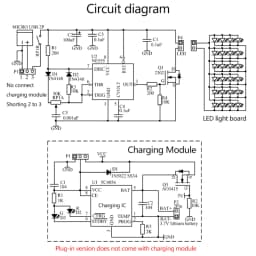
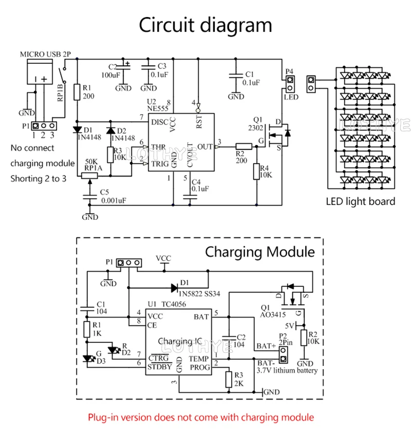
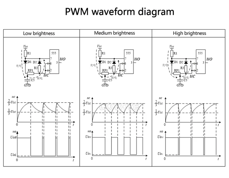
This is a kind of PWM dimming table lamp based on 555 timer. PWM is called pulse width modulation signal, using the width of the pulse to adjust the brightness, the more windowed the pulse, the higher the height, the narrower the pulse width, the darker the brightness. By dry less amount of power as heat is wasted, the efficiency can reach 90%. The basic frequency of this circuit is around 30KHz, so there is no strobe. The circuit schematic is shown below. (Note: Plug-in version does not contain the charging module circuit, the installation will be P1 port 2 3 pin short)
The circuit consists of charging circuit, PWM signal generator, LED lamp board 3 parts, the circuit potentiometer RP1 is with switch, the circuit diagram RP1B is the potentiometer switch part, RP1A is the potentiometer part, when the potentiometer switch off, the whole 555 circuit is not connected to the power supply, the lamp is in the off state. When the potentiometer is turned on, the power supply is turned on to supply power to the circuit. The power supply charges the capacitor C5 through R1, D1 and RP1, at this time, because the resistance of RP1A's pin 1-2 is small and the resistance of pin 2-3 is large, so the charging time is fast and the discharging time is slow, the output pulse duty cycle of 555's pin 3 is small and the brightness is low. When the potentiometer is rotated clockwise, the resistance of RP1A pin 1-2 gradually increases and the resistance of pin 2-3 gradually decreases, so the charging time of capacitor C5 becomes slower and the discharging time becomes shorter, and the pulse duty cycle of 555 pin 3 gradually increases and the brightness increases. 555 output PWM signal drives the LED light through N-channel MOS tube Q1.
The charging circuit uses the 4056 charging IC. 4056 is a linear charger circuit designed specifically for a Li-ion or Li-polymer battery, using the chip's internal power transistors to charge the battery at constant current and voltage. The charging current can be set with an external resistor R3, which has a resistance value of 2K, resulting in a charging current of 580mA. D2 and D3 are charging indicator LEDs in the circuit, D2 lights up in red when in charging state, and D3 lights up in green when the voltage is full. When plugged in, the 5V power supply is connected to the charging module to charge the rechargeable battery, the G terminal of large MOS tube 01 (A03415) is connected to the positive power supply, so the MOS tube is cut off and the rechargeable battery cannot be output to the 2 pin of P1, but directly from the positive power supply (2 pin of P1) to the 555 circuit through D1 (3 pin of P1), when the power supply line is unplugged, as the G terminal of MOS tube Q1 ( A03415) of the G terminal has no voltage for low level, so the MOS tube conducts and the battery supplies power to the 555 circuit through Q1 (pin 3 of P1).
The charging module and rechargeable battery are optional accessories. If the charging module is not installed, it is necessary to short circuit 2 and 3 of port P1 on the 555 control circuit, so that the power is directly connected to the switch of the potentiometer (RP1B) The automatic switching will be done by the charging module after the charging module is installed.
The 555 in the circuit is a CMOS RC timer that has significant performance based on the standard NE555 with low operating current, wide operating voltage, low threshold, trigger and reset circuitry, no disturbance to the supply current during output conversion, higher frequency performance and no need to decouple the control voltage for stable operation.
Customer Reviews
No reviews yet
DIY Electronic Kit NE555 LED Dimming Table Lamp Kit PWM Circuit DIY Soldering Assembly 8.5W 5V 2A With Switch Potentiometer
51.32$
25.66$
Quantity:
1
Availability:
Color