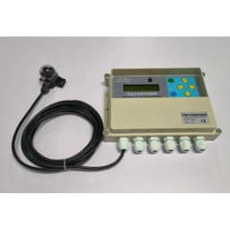
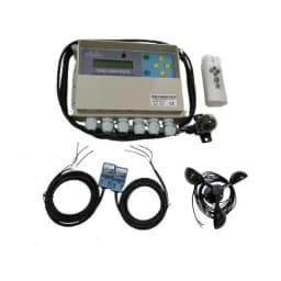
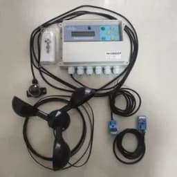
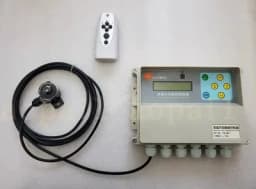
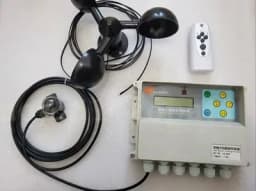
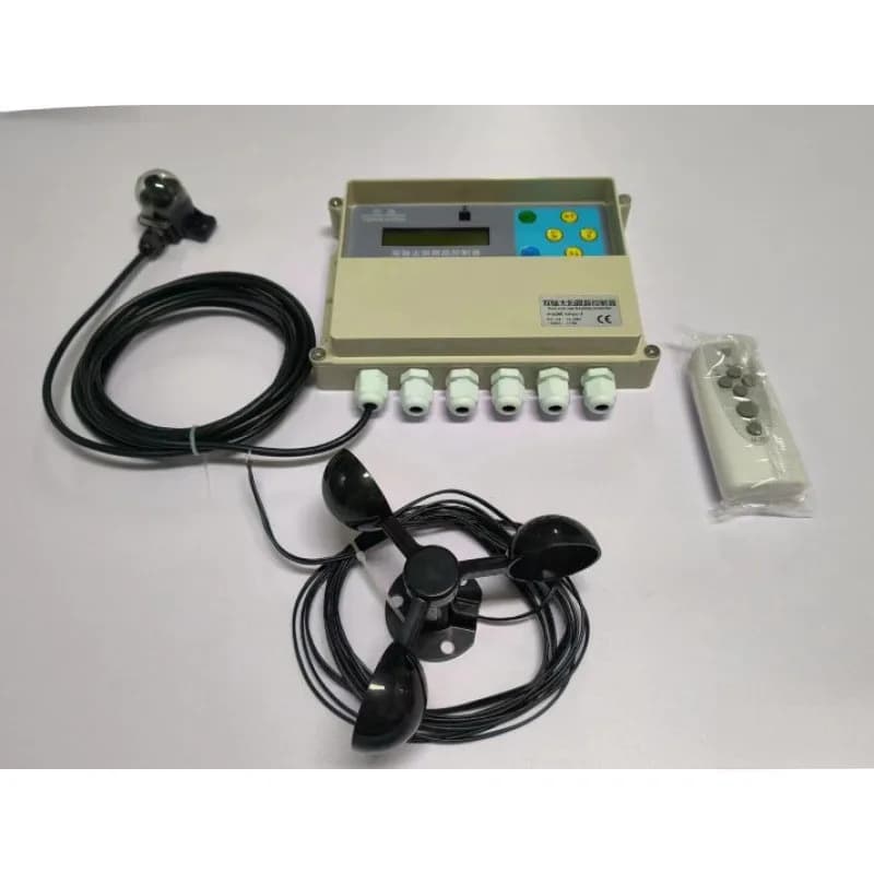
Dual Axis Solar Tracker Controller Automatic Sun Two-degree-of-freedom Platform Tracking System
26.56$
26.56$
Quantity:
1
Availability:
Color
Card Payments
Crypto Payments
Easy return
Reliable Shipping
modname=ckeditor
New Solar Tracker Dual Axis Controller Solar Automatic Tracking System
Two-degree-of-freedom Platform Tracking Sun Tracker
Note: This controller is a 2022 dual-axis tracking controller. Because the detailed description introduced below is too complicated, in order to prevent you from getting dizzy, here is a brief description of the function of this controller: this controller can control dual degrees of freedom The platform tracks the sun in real time, and has the ability to flatten in the wind, flatten in the center on cloudy nights, applicable to both the northern and southern hemispheres (the manual is marked for use in the northern hemisphere, if the southern hemisphere is used, reverse the east and the north to the north and south), button control and infrared wireless manual control Functions, as well as various parameters can be adjusted freely, LCD screen parameter display and other functions. The requirements for the platform are: it must be a platform driven by two brushed DC motors, and the platform must have a limit function (external limit is recommended, or a controller can be introduced for limit).
Electrochemical experiment one-stop shopping Store
XMYC—3 double shafts sunshine tracing controller operating specification
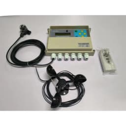
This controller is double shafts sunshine tracing controller, it adopt the high precision internal and external ring hole type sensor to detect the sunshine direction, process analyse judgement through the SCM electric circuit on the controller to the sensor signal, execute the whole process of tracing sunshine through the corresponding motor of electric relay assembly control platform on the electric circuit board, at the same time, it still has the functions such as leveling when meet wind (need optionally configure the air speed sensor), reset in cloudy day or night, adopt the English liquid crystal display to indicate the corresponding parameters, and able to use the keys on the controller or keys of infrared controller (need optionally configure the remoter) to set various parameters.
This controller corresponding platform required to be double freedom platform, the drive motor of platform is DC brush motor, the motor voltage is 12V or 24V, current of single motor must be less than 15A (default that each one shaft configure 10A fuse). Four direction of platform all should have limit switch.
DC IN:10-28V DC OUT=DC IN I MAX<15A
The controller formed with the below main components:
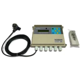
1. Main controller +sunshine sensor:
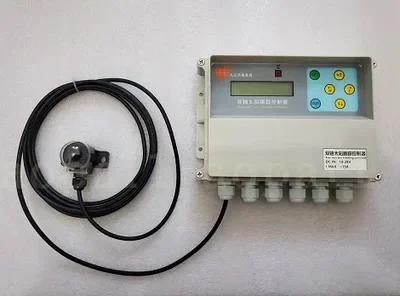
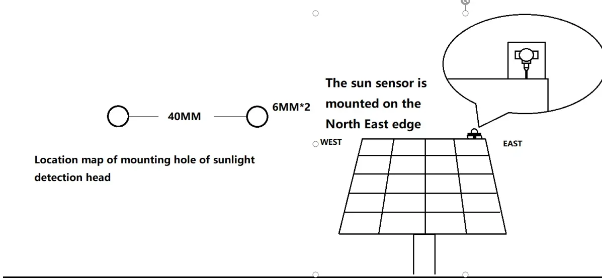
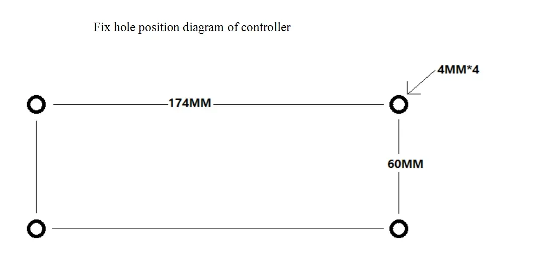
Mounting holes of main controller 4MM: left and right hole distance: 174MM, up and down hole distance: 60MM
The product adopt the water proof box as the external shell, it has raining proof performance when vertically mounted, the max has 6 pieces water proof wire outlet port and used in circuit connection, all circuits connection on the main board adopt terminal wiring method, the up cover has screen indication and six operating keys, able to observe the parameters and process manually operating or parameter setting.
2. Sunshine sensor:
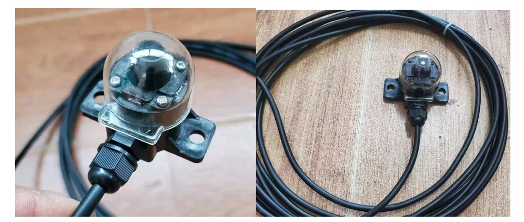
The unique deep hole type internal and external double inspection method generate different sunshine radiation voltage value at four directions through shielded by the middle pheasant shape cap, transmit to main board through 5 cores cable with 3m length. The mounting method is 2 pieces M6 bolts which distant 40MM fix and configure the transparent cover, it has a certain dust proof and water proof function.
3. Wind speed sensor: (Optionally configured parts)
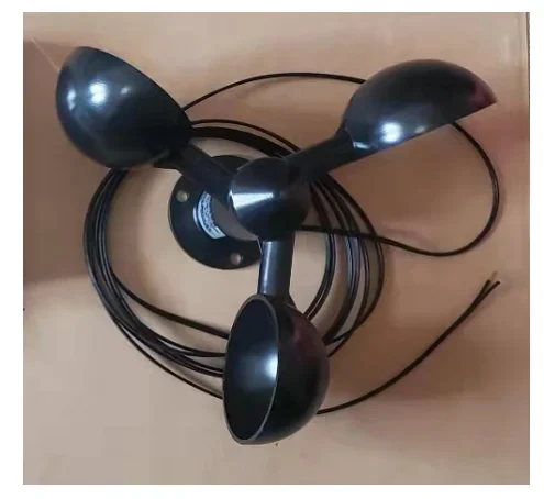
Wind speed sensor used to test the environment Wind speed, the controller control platform drive to the position where able to avoid wind to protect the platform when Wind speed achieved the protection value which set by the controller, the default air speed sensor configured the wire length is 3m. (If the customer self configured the Wind speed sensor then need select and use the voltage signal type Wind speed sensor)
4. Infrared remoter (optional part)
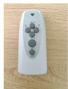
Use 2 pieces #7 batteries,
The detail instruction:
Each function of control board as below:
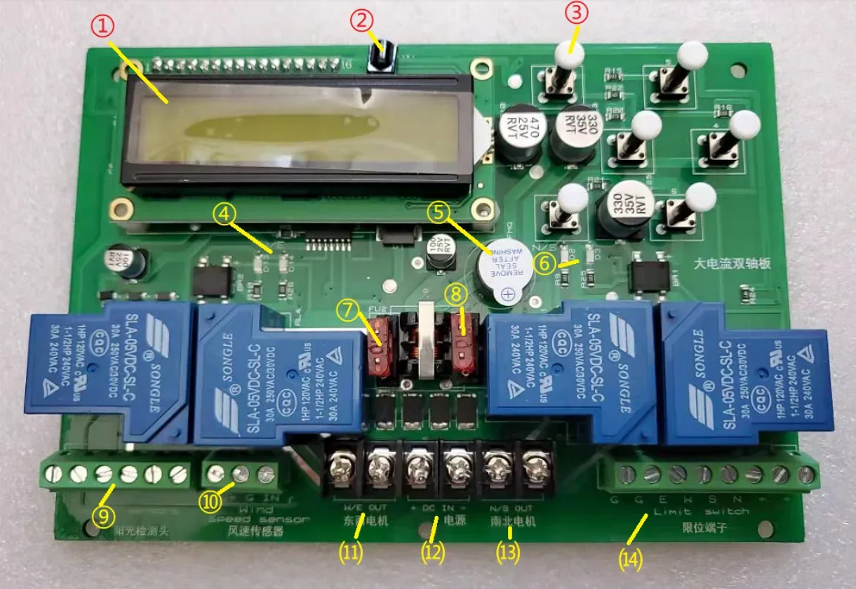
1. Display screen
2. Remote receive head
3. Operating button
4. Output indicate lamp of east and south shafts
5. Buzzer
6. Output indicate lamp of south and north shafts
7. Fuse of of south and north shafts
8. Fuse of south and north shafts
9. Sunshine sensor joggle (from left to right are ground, east, west, south, north and front)
10. Wind speed sensor joggle (from left to hundred are supply power V+, GND, signal input)
11. Motor joggle of east and west shafts
12. Power supply input (12 or 24V DC, left positive and right negative)
13. Motor joggle of south and north shafts
14. limit terminal joggle (from left to right are ground, ground, east, west, south, north, front and front)
Mounting methods:
Sunshine sensor mounting:
Mount the sunshine sensor on the platform and plane action along with the platform, attention it need parallel to the up plane of platform, the wire outlet hole direction on the test head need be face to ground when platform vertical.
The test head should do best to mount at north east edge of platform when at the northern hemisphere. It should be south east edge when at the southern hemisphere.
Main control box mounting:
The main control box should be mounted nearby the base pile of platform, needn’t action along with the platform, do best to make ensure it will not be raining, sunshine and other affection, the wire outlet hole downward to prevent the rain water flow in. The best is able to observe and operate conveniently.
Wind speed sensor mounting:
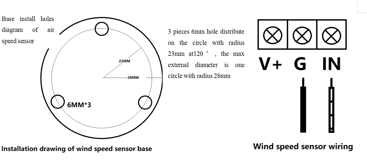
The Wind speed sensor should be mounted nearby the platform, where able to validly blowing by the air force. Don’t close to wall corner or ground, the better is one pile support mounting.
Lead the wire of Wind speed sensor into control box and connect well according to the marks, remain margin and firmly mounted.
Attention that standard configured Wind speed sensor wiring method are: black with white stripes connect the signal input IN, black connect G, V+ supply power needn’t connection.
If outsourced the other factory Wind speed sensor then discriminate the V+, negative, signal, connect in according to specification marks then okay.
The Wind speed sensor terminal V+ on this control board is power supply voltage value (12-24V). Required the signal output must be voltage type and the signal range less than 5V.
Wiring method of limit switch:
Limit switch is necessary, the below has A and B two methods to process limit (limit switch need be purchased yourself).
A: adopt the outer configured limit switch control method to realize the limit, the method of outer configured is: adopt the micro motion switch which has normally closed contact to place at four position where need be spaced on the platform, directly control the supply power circuit of the corresponding motors to realize the limit, shown as the below diagram:
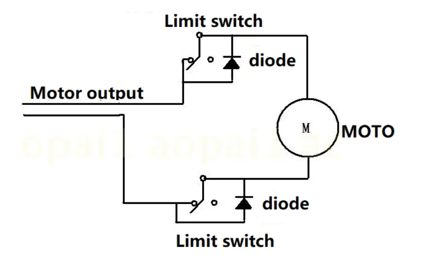
Use this method need pay attention whether limit switch and load current capacity of paralleled diode are enough, if use the electric push rod with limit then needn’t this method, because internal of electric push rod configured this method A limit electric circuit.
B: adopt the method that lead the limit signal in controller to realize limit, then need use the limit switch which has normally open contact, this switch jack up when one direction arrived limit, switch close conducted, short connect the ground (G) of limit terminal with the terminals at the corresponding direction, now the output at this direction will stop.
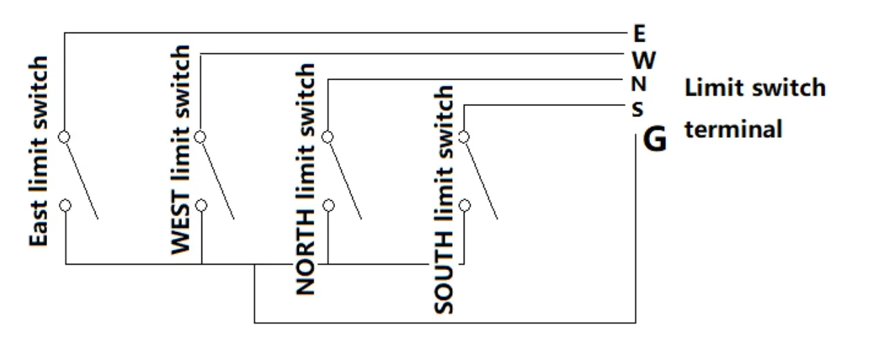
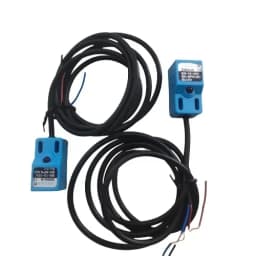
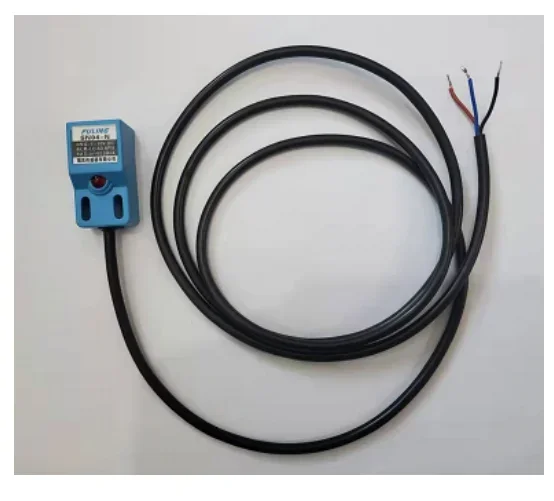
This controller also able to connect in three wire type NPN type approach switch, able to connect the supply power+terminal into +terminal of limit terminal when use this type switch as limit then okay, the others same to method B.
(for example, when the company purchases the proximity switch, the wiring definition is: Brown +, blue G, black limit signal.) Note that the top is the sensing area. When there is metal within 5mm, the limit signal will be output.
The double shafts drive motor should be able to drive the platform and smoothly move in the corresponding range under the situation that not connect control board and independently supply power, only can connect the motor on the corresponding shaft motor terminal on the control board under this situation, attention that east-west shaft motor and south-north shaft motor can’t error connected.
Running debugging:
Confirmed that sunshine sensor, air speed sensor, limit switch and both shaft motor all connected on position then can connect the power supply on control board and debugging, power supply voltage 12 or 24V (subject to the used motor rated voltage), the supply power current should be enough to meet the max current requirements of two motors.
Connect power supply, buzzer send out one DI sound, now the controller should be power on and working, the display screen should indicate:
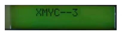
Then the controller will enter into various status according to the detail sensor feedback parameters.
But now we should firstly test whether direction of motors are correct, so must firstly enter into manual to test, one time press SET key then will enter into the below manual MT page:

Now the key →/←/↓/↑ able to control the platform move to east/ west/south/north directions respectively, at the same time, the display screen will indicate E/W/S/N to represent them. If the action direction of platform not accordance with the manually control direction then exchange the corresponding wiring then okay, use the manual function test the all action range of platform, include that after limit status function all should be able to test normally then able to process the further more each item work.
The corresponding output indicate lamp on the controller main board will lighting when manually control the platform. Press QUIT key then can withdraw the manual.
The screen background lamp will lighting 10s firs then extincted when key operating, if long time press QUIT key 5s then can long term start or close the display screen background lamp.
Parameters setting:
We enter into parameter setting after confirmed the motor wiring correctly, process necessary inspection and setting at some parameters, long time press SET key 5s and loosen at the non manual control interface then will enter into parameter setting page, attention the time parameter unit T all are second. Threshold value unit V all are voltage:
Especially reminding: for the below parameter setting interface, key →/← able to shift the parameter items, key ↓/↑ able to add and reduce the parameters, long time press then quickly add and reduce the parameters, press QUIT key then withdraw and save. The below parameter item not described in sequence to convenient for the customers understand the parameter definition.
V2/T3/4/5/6/7: air speed protection related parameters:
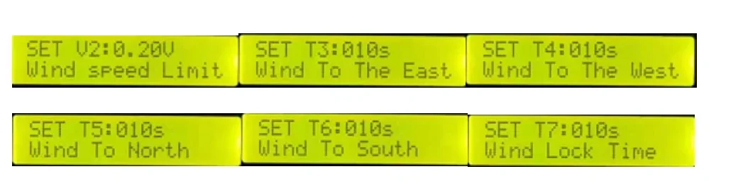
When air speed sensor transmitted signal voltage value higher than V2 then will enter into air speed protection control status, the sequence as below:
(1) The time T3 of drive the platform toward east immediately, at the same time, execute the time T5 of platform toward north.
(2) Then execute the time T4 of drive the platform toward west, at the same time, execute the time T6 of platform toward south after T5 execution finished.
(3) Time T7 is the remain lock time after finish execute the above process, the device keep standby within time T7, if air speed continue exceed the V2 value, then time T7 fully filled again.
(4) If air speed lower than V2 value then withdraw the air speed protection status after time T7 end. If cloudy day status after air speed protection action execution finished and during the T7 count down then lock and not withdraw. The max parameter able to set at 999, the min able to set at 1.
Able to execute the platform to the users expected angle and position when air speed exceed limit through reasonably set the above parameters.
The shift formula of leave factory configured air speed sensor signal voltage and air speed: V*25=m/s V*25=m/s
Example: air speed sensor indicated value F=0.2, means the current air speed about 5 m/s
Example: V2 value set at 0.18, means the air speed exceed the limit threshold value set at 4.5 m/s
V1/V3/T13/TX/TY parameters definition:
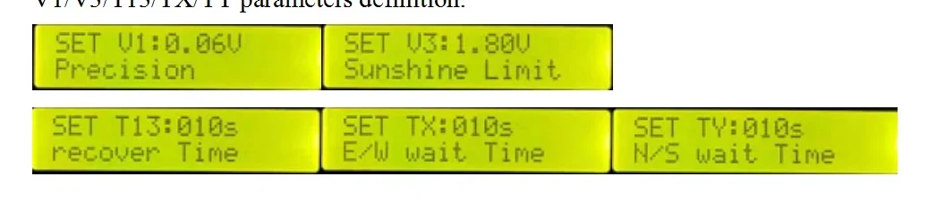
When sunshine sensor tested any one direction voltage higher than V3 value then judge it enter into fine day, now process timing, if the time continue higher than V3 value and achieved time T13 (s), then enter into fine day tracing status, the controller control each shaft motor action to achieve the purpose that align to sunshine, V1 value is tracing precision, more smaller this value then more higher precision, but required the platform mechanical precision also able to achieved a certain degree then okay. Means of TX/TY parameters is that avoid the tiny light changes caused the device frequently repeat the tracing action when align to the sunshine during automatic tracing the sunshine, set one interval time, means this shaft enter into dormant time after aligned the sunshine, recheck the sunshine position and tracing after waiting this time passed, the common sunshine movement also be most slow, set interval time also able to save the power.
TX: enter into interval waiting time after east-west shafts aligned.
TY: enter into interval waiting time after south-north shafts aligned.
Able to make ensure the controller able to quickly and correctly enter into tracing status at fine day through reasonably set the above parameters.
T8/9/10/11/12 cloudy day r night platform reset parameters setting:
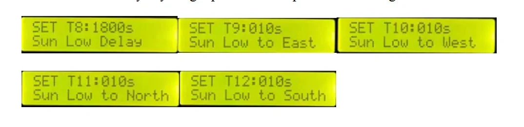
Judge at weak sunshine when sunshine test head tested any one direction voltage value lower than V3, now it will dormant originally and enter into T18 count down (s), if sunshine value still not recover to above V3 within this count down time, then execute the reset action after the count down ended, the sequence is:
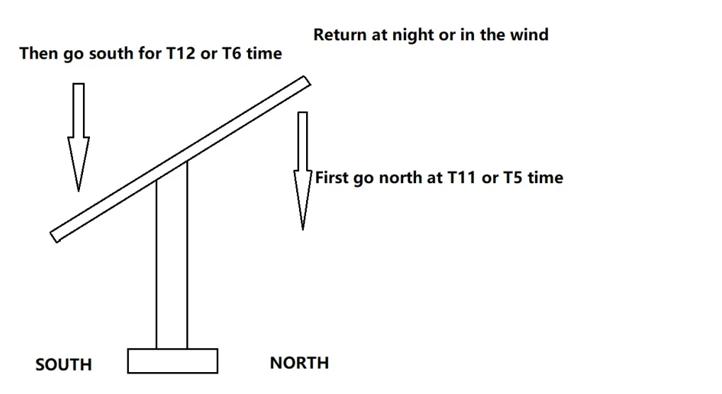
(1) Running toward east time T9, at the same time, execute the time T11 toward north.
(2) Then execute time T10 toward west, execute time T12 toward south after T11 finished.
T8 able to set max 9990, the other parameter able to set max 999, also able to set min 1.
Able to make platform appointed to the users expect angle or position in weak sunshine or night through reasonably set the above parameters.
Press QUIT key to withdraw and save after parameters setting finished.
Equipment automatic working logic sequence:Equipment automatic working logic sequence:
The controller will judge the back transmitted each item data of sensor and process automatically control when equipment power on, the among able to divided into the below several situation:
SH: if sunshine sensor tested any one direction voltage value higher than V3 value then enter into fine day automatically tracing status after accumulate timing T13 parameter setting time:

The controller will contrast the east, west, south and north voltage value of sunshine sensor under this status, control the platform, it will enter into TX/TY interval waiting time when one shaft aligned. Repeatedly contrast and control after this time count down ended. To realize the tracing process of this platform.
SL: Enter into cloudy day or night status when sunshine sensor tested any one direction voltage lower than V3:
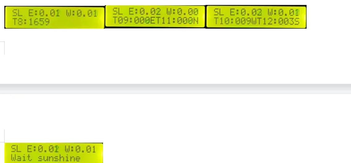
Firstly enter into T delay, if occur that higher than V3 within T8 time then withdraw this status, if continue lower than time achieved time T8 then execute the stipulated actions:
Toward west time T10 after executed toward east time T9, at the same time, toward south time T12 after executed toward north time T11. The buzzer will sounding to wake up at a certain frequency under this status.
Enter into that waiting sunshine status after execute the action finished.
FS: enter into air speed reset status when air speed sensor tested air speed value higher than V2:
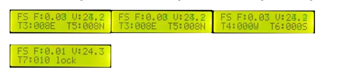
Judge the air speed over limit when air speed sensor signal voltage higher than setting V2 value and continue 3s, now the controller execute the air speed reset action, the sequence are:
Toward east time T3 then execute that toward west time T4, at the same time, execute that toward north time T5, then execute that toward south time T6. The buzzer will sounding to wake up at a certain frequency under this status.
Enter into lock count down T7 after execution finished, if air speed sensor signal voltage exceed V2 value again within this count down time then this count down T7 timing lock again, if this time is cloudy day status then always lock to sunshine recovered.
Able to alternately display various parameters on the screen through key →/← under the above working status, include: voltage value at east, west, south and north direction of sunshine sensor, air speed sensor signal voltage value, the current supply voltage value, etc.
About the night reset and wind reset, the sequence logic shown as the below picture:
First step:First step:
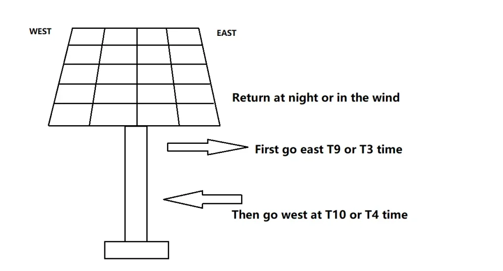
Second step:
Electrochemical experiment one-stop shopping Store
The liquid crystal screen will occur the code, definition and explain of each item parameter:
AT: automatically tracing status, the device automatically tracing sun under this status
TX:the east west shaft under automatically tracing status enter into waiting time period after aligned, the device will not action within this time period. Advise: 100
TY: the south north shaft under automatically tracing status enter into waiting time period after aligned, the device will not action within this time period. Advise: 100
E: east W: west S: south N: north (indicate device move the corresponding direction)
V: real time voltage value of supply power.
FS: air speed exceed the setting value, enter into that leveling in wind and reset status.
FS LOCK: lock status after air speed reset.
F: real time air speed voltage value, the unit is V.
SH: fine day automatically tracing status.
MT: manual operating status, the remoter key 1/2/3/4 corresponding to north/south/west/east direction manually move under this status
SL: weak sunshine, represent that current controller regard weak sunshine, means that will enter into dormant status and waiting the sunshine occur again.
T3:the time value of device drive toward east when execute the appointed action of air speed over limit, unit is second.
(Advised setting value: the whole process used time when platform from east to west*1.2 times)
T4:the time value of device drive toward west when execute the appointed action of air speed over limit and after continue the time T3, unit is second.
(Advised setting value: the required time that platform walk from west to east to the east west shaft posture which you want the platform executed)
T5: the time value of device drive toward north when execute the appointed action of air speed over limit, unit is second.
(Advised setting value: the whole process used time when platform from south to north*1.2 times)
T6: the time value of device drive toward south when execute the appointed action of air speed over limit and after continue the time T5, unit is second.
(Advised setting value: the required time that platform walk from north to south to the south north shaft posture which you want the platform executed)
T7: controller self lock time after finish execute the air speed over limit stipulated actions, this function is prevent that air speed influence is interval, caused the device frequently execute the action/tracing, if air speed exceed the value again with self lock time then this time will timing again immediately, make the device not frequently action, unit is second.
(Advised setting value: 600)
T8: weak sunshine continue time delay value
(Advised setting value: 1800)
T9: the time value of device drive toward east when execute the weak sunshine appointed actions, unit is second.
(Advised setting value: the whole process used time when platform from east to west*1.2 times)
T10: the time value of device drive toward west when execute the appointed action of weak sunshine and after continue the time T9, unit is second.
(Advised setting value: the required time that platform walk from west to east to the south north shaft posture which you want the platform executed)
T11: the time value of device drive toward north when execute the weak sunshine appointed actions, unit is second.
(Advised setting value: the whole process used time when platform from south to north*1.2 times)
T12: the time value of device drive toward south when execute the appointed action of weak sunshine and after continue the time T11, unit is second.
(Advised setting value: the required time that platform walk from north to south to the south north shaft posture which you want the platform executed)
T13: the sunshine recover continue time setting value after happened weak sunshine status, unit is second.
(Advised setting value: 10)
V1: tracing precision setting, this value is set the tracing precision region voltage value, means that controller regard need move device or aligned the sun when how many different V of east/west and south/north tested voltage value, more smaller this value then more higher precision, more lower precision reversely, need setting according to the characteristics of the platform.
(Advised setting value: 0.06)
V2: air speed start control voltage value, this value is the controller set air speed start control threshold value, the control think it need act immediately to protect the platform when air speed sensor output voltage higher than this value.
(Advised setting value:subject to the parameter corresponding table of air speed sensor.) (The advised setting value of our company configured sensor is 0.15)
V3: weak sunshine start control voltage value, this value is the controller set weak sunshine threshold value, controller think current sunshine is weak when four direction voltage value of sunshine test head no any one higher than this value, no power generate value then cancel tracing, if device still tracing sun in cloudy day then can suitably improve this value, make controller judge it as cloudy day.
(Advised setting value: 1.80)
Electrochemical experiment one-stop shopping Store
Notices:
1. The staffs should far away platform to avoid unexpected hurt when debugging and operating platform.
2. Should avoid install and debug the equipment in thunder and raining day.
3. All should cut off power supply when wiring under any situation to avoid short circuit damages.
Customer Reviews
No reviews yet
Dual Axis Solar Tracker Controller Automatic Sun Two-degree-of-freedom Platform Tracking System
26.56$
26.56$
Quantity:
1
Availability:
Color