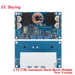
LTC3780 DC-DC 5-32V to 1V-30V 10A 8A 3A Automatic Step UP Down Converter Boost Buck Charging Power Supply Module Solar Charger
4.96$
3.6$
Quantity:
1
Availability:
Color
Card Payments
Crypto Payments
Easy return
Reliable Shipping
Product introduction:
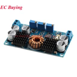
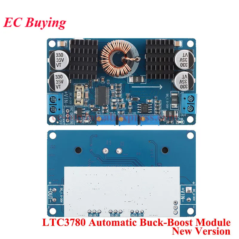
This power supply is a high-efficiency regulated power supply module. When the input voltage is lower than, higher than, or equal to the output voltage, the output voltage can remain stable. For example, if the output is set to 12V, when the input voltage changes between 5-32V, the output voltage will remain unchanged at 12V. This module has perfect protection function and can be applied to solar charging.
Product parameters:
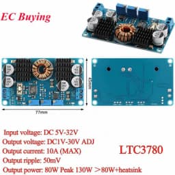
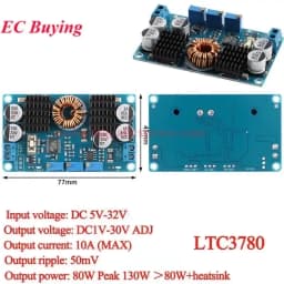
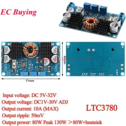
1. Input voltage: DC 5V-32V, the recommended voltage is above 10V
2. Output voltage: DC1V-30V continuously adjustable;
3. Output current: 10A (MAX) within 7A for a long time;
4. Output power: long-term 80W, peak 130W, please strengthen heat dissipation if it exceeds 80W;
5. Output ripple: 50mV (12V to 12V, measured at 5A);
6. Input reverse connection protection: None, if necessary, please connect a Schottky diode in series with the input terminal;
7. Output backflow prevention: None, if it is used for battery charging or the load is an inductive load with its own, please connect a Schottky diode in series with the output;
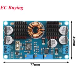
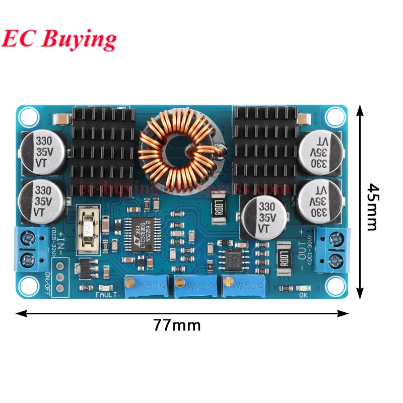
8. Size: 77.6*46.5*15mm
9. Short circuit protection: Yes
Instructions for use:
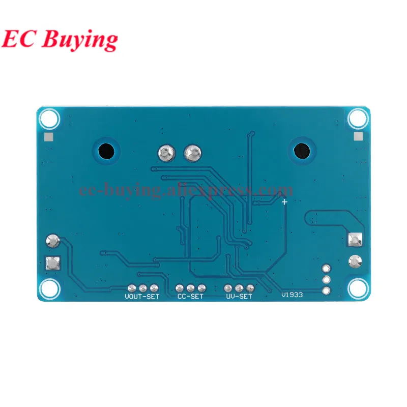
1. Battery undervoltage protection adjustment method: (Take 12V lead-acid battery to set 10V undervoltage protection and turn off the output as an example) The input is connected to the regulated power supply and adjust to 10V, and adjust the undervoltage protection potentiometer (clockwise increase, counterclockwise decrease) ) Until the fault indicator (red light) just lights up, the setting is successful; in this way, when the battery is discharged to 10V, the power supply will be automatically cut off to protect the battery from damage.
Note: If it is not battery powered, you can skip the setting;
2. The output voltage adjustment method: the input is connected to the power supply (the voltage is higher than the undervoltage protection value), the red light is off, the blue light is on, the output is connected to a multimeter, and the output voltage potentiometer is adjusted (clockwise to increase, counterclockwise to decrease), Until the required voltage;
Note: Normally, the red light is off and the blue light is on. Otherwise, it is faulty. Input under-voltage protection, output over-current protection, and output short-circuit protection. Please troubleshoot and re-power on.
3. Output current adjustment method: (take 12V input to charge 12V lead-acid battery, charging current 5A as an example). Connect the input to 12V power supply, set the current to the multimeter, output and connect to the multimeter (the red test lead is connected to the output positive, the black test lead is connected to the negative, Short-circuit the output directly. It is recommended to use a current gear above 15A to prevent burning of insurance), adjust the constant current potentiometer (clockwise increase, counterclockwise decrease) until the current shows the required value of 5A, remove the multimeter, and connect it The battery can be charged normally. If using an ammeter to adjust the output current, refer to the corresponding wiring of the ammeter for correct wiring and debugging.
Note: For constant voltage equipment, only the maximum output current needs to be set.
Introduction to synchronous rectification technology:
Synchronous rectification is a new technology that uses a dedicated power MOSFET with very low on-resistance to replace the rectifier diode to reduce rectification losses. It can greatly increase the efficiency of the DC/DC converter and there is no dead zone voltage caused by the Schottky barrier voltage. Power MOSFETs are voltage-controlled devices that have a linear relationship in volt-ampere characteristics during turn-on. When using a power MOSFET as a rectifier, it is required that the gate voltage must be synchronized with the phase of the rectified voltage to complete the rectification function, so it is called synchronous rectification. The synchronous rectification technology greatly reduces the rectification loss at the output end of the switching power supply, thereby improving the conversion efficiency and reducing the heating of the power supply itself.
Parameters:
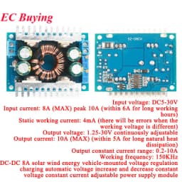
Module nature: non-isolated synchronous rectification automatic buck-boost module
Input voltage: DC5-30V
Input current: 8A (MAX) peak 10A (within 6A working for a long time)
Static working current: 4mA (error will occur when operating voltage is different)
Output voltage: 1.25-30V continuously adjustable
Output current: 10A (MAX) (for long time natural heat dissipation within 5A, please use derating when high voltage output, please use heat dissipation or derating for module temperature over 65 degrees)
Output constant current range: 0.2-10A
Working temperature: -40-+85 degrees
Working frequency: 150KHz
Conversion efficiency: typically 91%, up to 93%
Overcurrent protection: Yes
Short circuit protection: Yes (current limiting protection)
Over temperature protection: Yes (automatically reduce output voltage after over temperature)
Input reverse connection protection: none, (if necessary, please input the diode in the input)
Output anti-backflow: Yes, there is no need to add anti-reverse diodes for charging.
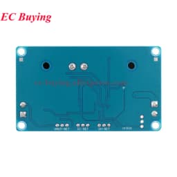
Wiring method: terminal output, (IN is input, OUT is output)
Module size: 60mm*53mm*22mm (length, width and height)
Application range:
This module can be applied to areas where the input voltage is relatively large and the output requirements are relatively stable. Such as:
1.12V battery (10-14V) regulated output 12V, power supply for 12V equipment, 24V battery stable 24V: can be used as vehicle power supply
2. Solar panel voltage regulation, the voltage fluctuation of the solar panel is relatively large, this module can regulate the output, supply power to the device or charge the battery.
3. Drive high-power LED lights, constant current drive, such as 12V battery drive 4 string LED lights, this time LED and battery voltage are not much different.
Application: LED drive, wind energy solar, car battery charging
Output current adjustment method:
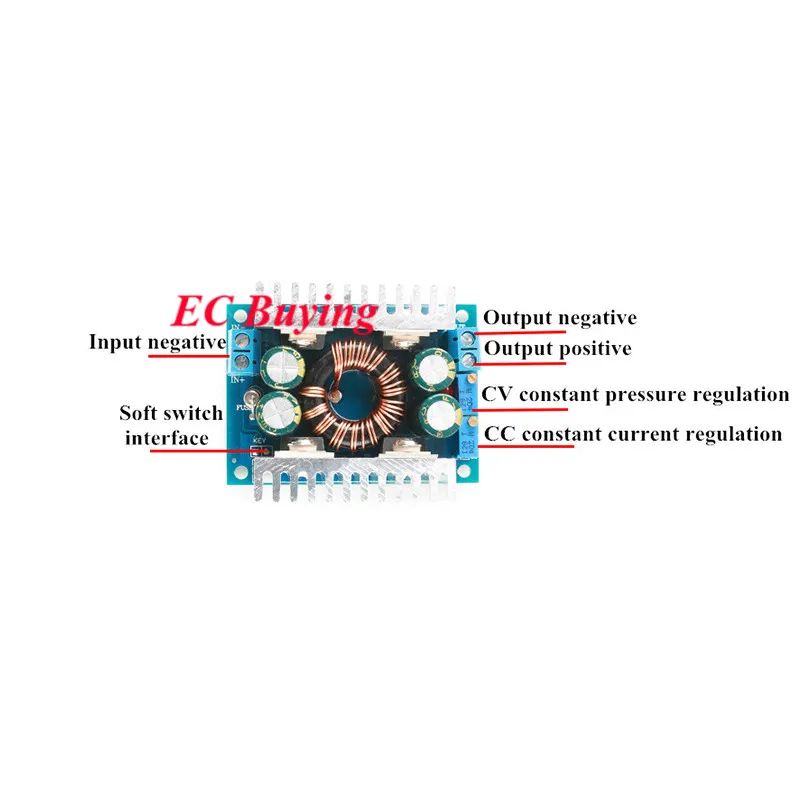
1. Adjust the CV potentiometer and set the output voltage to the voltage you need according to your load requirements.
2. Set the CC potentiometer counterclockwise for about 30 turns (ie set the output current to the minimum), connect the LED, and adjust the CC potentiometer to the current you need. For battery charging, after the battery is discharged, it will be connected to the output and adjust the CC to the current you need. (Be sure to use the discharged battery when charging, because the battery is left in the battery.) More, the charging current is smaller.) Please do not use short circuit to adjust the current, the circuit structure of the module can not be adjusted by short circuit.
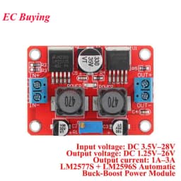
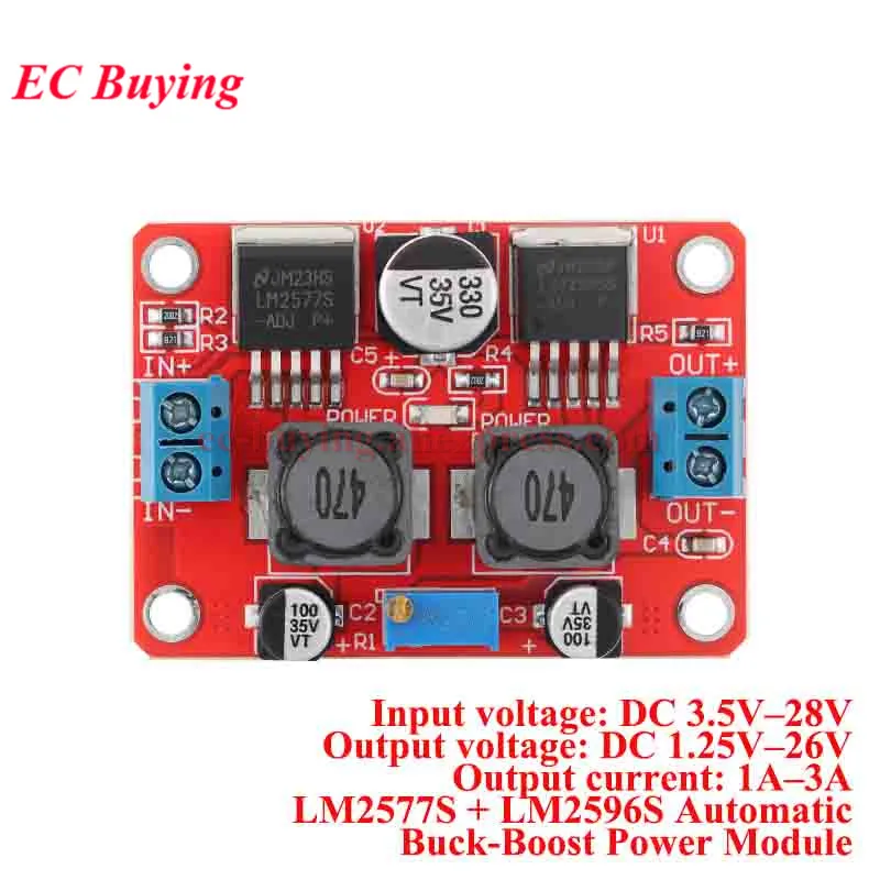
Input voltage: DC 3.5V–28V
Output voltage: DC 1.25V–26V
Output current: 1A–3A
LM2577S + LM2596S Automatic Buck-Boost Power Module
Customer Reviews
No reviews yet
LTC3780 DC-DC 5-32V to 1V-30V 10A 8A 3A Automatic Step UP Down Converter Boost Buck Charging Power Supply Module Solar Charger
4.96$
3.6$
Quantity:
1
Availability:
Color